
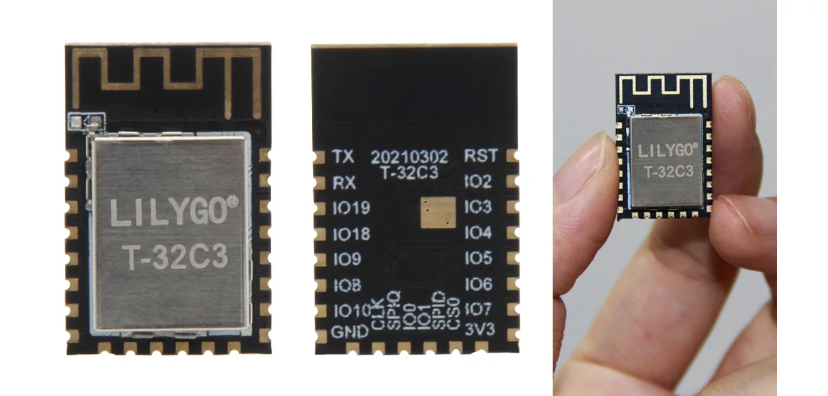
We’re slowly starting to see more hardware-based on ESP32-C3 RISC-V processor, and LILYGO T-32C3 is a compact module based on the WiFi & Bluetooth LE processor that includes 4MB flash and a PCB antenna.
I’d expect T-32C3 to be eventually found in the company’s smartwatches and development boards, and it joins other ESP32-C3 modules from AI Thinker.
LILYGO T-32C3 module specifications:
- SoC – Espressif ESP32-C3 RISC-V processor @ 160 MHz with 400 KB SRAM, 384 KB ROM, 8KB RTC SRAM, 2.4 GHz WiFi 4, Bluetooth 5.0 LE & Mesh
- Storage – 4MB flash
- On-board PCB antenna
- I/Os – 22x castellated holes with GPIO, 3x ADC, SPI, UART, I2C, Boot, Reset, 5V, 3.3V, GND
- Dimensions – 23 x 11 x 3.5 mm (4-layer PCB)
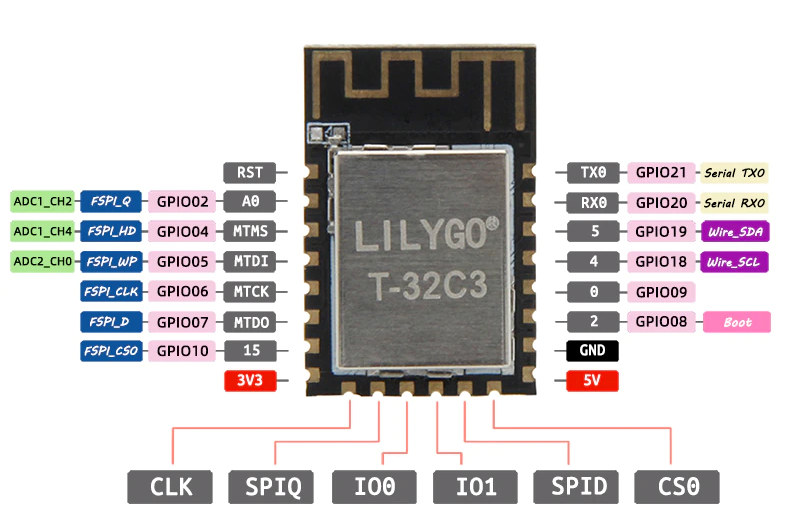
Note the USB interface is not listed in the specs, but USB DN and DP signals are located on GPIO18 and GPIO19 so USB should also be supported.
There’s no wiki for T-32C3, but you should be able to use the ESP-IDF framework or even ESP32 Arduino 2.0.0 core that was released a few days ago with ESP32-C3 (and ESP32-S2) support. Espressif posted a getting started guide for their own ESP32-C3 hardware a little while ago.
If you’d like to get the T-32C3 module, you can do so on Aliexpress for $2.88 plus shipping.
As a side note, there’s always a risk being an early adopter, and several people who purchased the NodeMCU ESP32-C3S_Kit development board with AI Thinker ESP32-C3 module got trouble using the serial console:
Hello everybody. I got a “ESP32-C3F-Kit” with a CH340 USB Bridge and a big problem: If I switch on serial monitor, the Board stops. Using the PCB schematics I could see the problem: The CH340 RTS output is connected via 4.7k resistor to ESP 32 EN and CH340 DTR output is connected via 4.7k resistor to ESP 32 GPIO9. If you switch on serial monitor, the CH340 outputs LOW at RTS and DTR and the ESP32-C3 is non-working because of LOW at EN. One workaround is to put a 2.2k resistors between EN and V3.3 and GPIO9 and V3.3. But there is another problem. The PCB print is wrong, the schematics is right. The GPIO9 pin is the pin labeled “IO10”. Now I have to press the buttons on the board to start flash programming like with my ESP32 boards, but serial monitor is working. Another solution is to remove the two 4.7k resistors from the ESP32-C3F-Kit board. I hope the manufacturer will do so soon.
I’m actually waiting for samples from AI Thinker, both ESP32-C3 boards and Unisound US516P6, and they told me they’d send everything once they have boards with the fix. I’m still waiting…

Jean-Luc started CNX Software in 2010 as a part-time endeavor, before quitting his job as a software engineering manager, and starting to write daily news, and reviews full time later in 2011.
Support CNX Software! Donate via cryptocurrencies, become a Patron on Patreon, or purchase goods on Amazon or Aliexpress